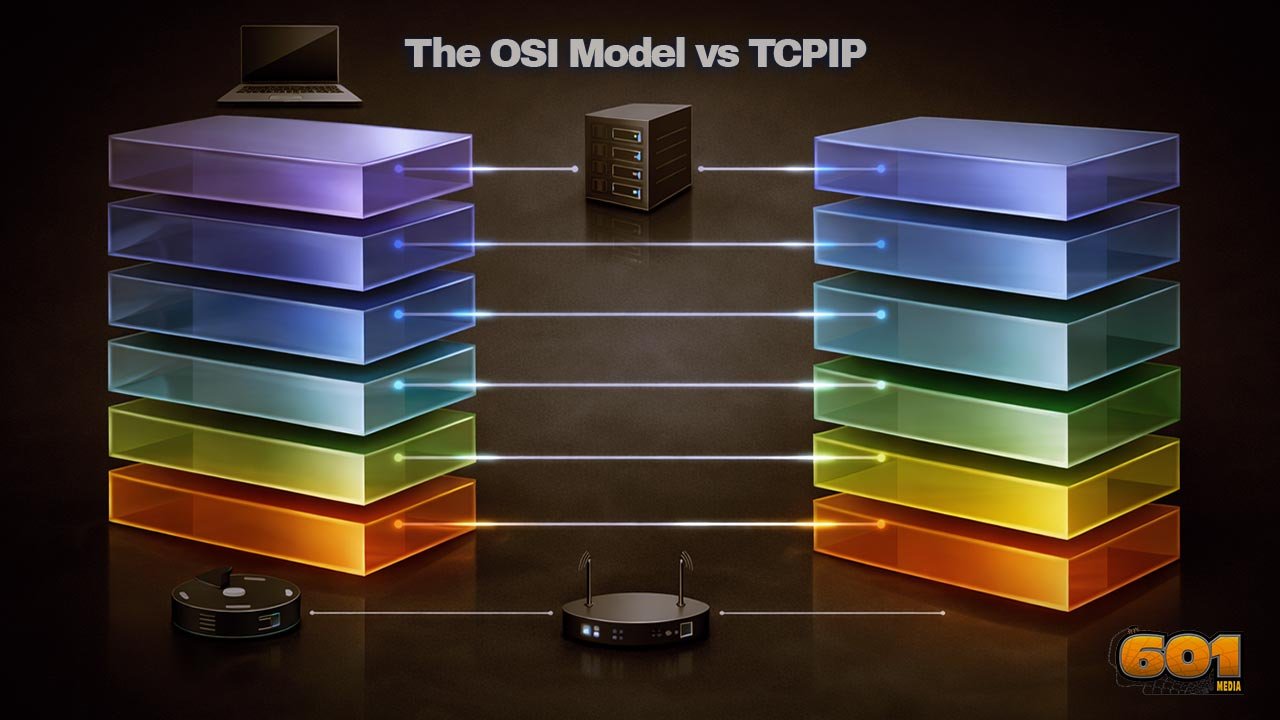
The OSI Model vs TCP/IP: What Every Techie Should Know
Two networking models dominate how we explain, design, secure, and troubleshoot modern systems: the OSI reference model and the TCP/IP (Internet protocol suite) model. The OSI model is a conceptual framework created to standardize how networked systems communicate, while TCP/IP is the practical protocol suite that powers the Internet. Tech teams routinely use OSI to reason about “where” a problem lives (layers), and use TCP/IP to understand “how” traffic actually moves (protocol behaviors). This guide connects the theory to the wire: layer mapping, real packet flow, common misconceptions, security implications, and how to use both models to make better decisions in architecture and operations.
Table of Contents
- Why Two Models Exist (And Why You Still Need Both)
- The OSI Model in Plain English
- The TCP/IP Model in Plain English
- OSI vs TCP/IP Layer Mapping That Actually Helps
- How Data Really Moves: A Web Request From Laptop to Server
- Troubleshooting With Both Models: A Repeatable Workflow
- Security Implications: Where Defenses Actually Attach
- Innovation and Technology Management View
- Top 5 Frequently Asked Questions
- Final Thoughts
- Resources
Why Two Models Exist (And Why You Still Need Both)
When engineers argue “OSI vs TCP/IP,” they’re usually arguing past each other. The OSI model is a reference model: a shared language for describing network functions in layers. TCP/IP is a protocol suite: real specifications that define how Internet communication works, and it’s the stack you’re almost certainly running in production.
In other words:
- OSI answers: “What categories of functions need to exist for communication to work end-to-end?”
- TCP/IP answers: “What protocols and behaviors actually move packets across interconnected networks?”
This difference matters because teams use models for different jobs:
- Architecture: communicating boundaries, responsibilities, and interfaces
- Troubleshooting: narrowing a failure domain fast
- Security: placing controls where they’re effective, measurable, and enforceable
- Innovation: deciding where new capabilities belong (protocol change, platform change, or product change)
The OSI Origin Story: Standardization First
OSI emerged from a standardization mindset: if the industry could agree on a universal layered model, vendors and governments could coordinate standards and improve interoperability. The OSI Basic Reference Model is formalized in ISO/IEC 7498-1, defining seven layers and the ideas of services, interfaces, and protocols as separate concepts. That separation is one of OSI’s strongest contributions: it helps you describe what a layer provides without immediately tying it to a specific protocol implementation.
The TCP/IP Origin Story: Working Code Wins
TCP/IP grew from research networks into an operational approach centered on interoperable implementations and pragmatic evolution. Its documents (RFCs) define behaviors and requirements across layers. For example, RFC 1122 organizes host requirements across the link, IP (internet), and transport layers, with companion RFC 1123 covering applications and support protocols. TCP/IP’s dominance is not because it is “more elegant,” but because it worked, scaled, and evolved while staying deployable.
The OSI Model in Plain English
Think of OSI as a mental model: it slices the messy reality of networking into seven function categories. Each layer describes “what problem is being solved here?” and “what does this layer offer to the layer above?”
Layer 1: Physical
This is the raw transmission of bits: voltages on copper, light on fiber, radio waves in Wi-Fi, modulation, connectors, pinouts, signal timing, and physical media constraints. If Layer 1 is broken, nothing else matters. Symptoms look like link down, no carrier, high error rates, or unstable connectivity.
What belongs here (conceptually):
- Cabling, transceivers, optics, antenna alignment
- Encoding, signaling, frequency/channel selection
- Bit timing and physical link establishment
Layer 2: Data Link
Layer 2 is about local delivery on the same network segment: framing, MAC addressing, switching, and error detection (like CRC). Ethernet and Wi-Fi live here in practice. Layer 2 defines “who on this local network should receive this frame?”
Typical Layer 2 concerns:
- Switching, VLANs, MAC tables
- ARP behavior (often taught near L2/L3 boundary)
- STP loops, broadcast storms, duplex mismatches
Layer 3: Network
Layer 3 is routing between networks. IP is the classic Layer 3 protocol for the Internet. Routing defines how packets traverse routers to reach remote networks. Layer 3 is where “end-to-end across many hops” begins.
Key Layer 3 ideas:
- Logical addressing (IPv4/IPv6)
- Routing and forwarding decisions
- Fragmentation/reassembly concepts (not always used the way people assume)
Layer 4: Transport
Transport handles end-to-end communication between processes (not just hosts). TCP provides reliable, ordered delivery with flow and congestion control. UDP provides lightweight, connectionless delivery. Layer 4 is where “ports” show up, enabling multiplexing multiple conversations over the same host IP.
Typical Layer 4 concerns:
- Connection establishment and teardown (TCP)
- Reliability, retransmission, ordering (TCP)
- Latency vs reliability tradeoffs (UDP vs TCP)
- Load balancer behavior (often spans L4–L7)
Layer 5: Session
Session is about managing dialogs: keeping track of conversational state, checkpoints, and recovery. In real systems, “session” often lives inside applications and libraries rather than a distinct network protocol layer. This is one of the reasons OSI is sometimes mocked—yet the concept is still real and operationally important (think: login sessions, token lifetimes, connection pooling, and negotiated capabilities).
Layer 6: Presentation
Presentation is about data representation: serialization, encryption formatting, compression, and character encoding. Again, modern stacks implement this mostly in libraries and application protocols rather than as a distinct network layer you can point to with a single box.
Examples:
- TLS record formatting and certificate-based identity (often taught as “L6-ish” in OSI terms)
- JSON vs Protobuf vs Avro serialization
- UTF-8 vs other encodings, content negotiation
Layer 7: Application
This is what users and services actually “speak”: HTTP(S), DNS, SMTP, SSH, and your custom APIs. Layer 7 is where business logic, identity, authorization, rate limiting policies, and API design decisions dominate outcomes.
A recurring misunderstanding: Layer 7 is not “apps” in the sense of “a mobile app icon.” It’s the application protocol layer: the rules of the conversation.
The TCP/IP Model in Plain English
TCP/IP compresses the conceptual layers into a smaller set aligned to deployable protocols. You’ll see 4-layer and 5-layer versions depending on whether someone splits “Link” into Physical + Data Link. What matters is the intent: TCP/IP focuses on what must work for internetworking.
RFC 1122 explicitly organizes requirements across the link, internet (IP), and transport layers, which is a good clue: TCP/IP is specification-first and behavior-first.
Link Layer
This covers the local network delivery mechanism: Ethernet, Wi-Fi, PPP, and more. It’s deliberately broad because many different link technologies exist, and TCP/IP does not demand a single universal link standard.
Operationally, “Link” includes:
- Frames on the local segment
- MAC addressing and local delivery
- MTU realities and what happens when paths disagree
Internet Layer
This is IP: addressing, routing, and datagram forwarding across networks. RFC 791 defines IPv4 as a connectionless datagram service designed for interconnected packet-switched networks and includes mechanisms like fragmentation and reassembly.
A useful mental shift: IP is not “reliable.” It is “best effort.” That design choice is why the Internet can scale across heterogeneous networks, but it also means reliability is pushed upward (usually into TCP or the application).
Transport Layer
This is TCP and UDP (and other transports). TCP is for reliability, ordering, and congestion control; UDP is for minimal overhead, often chosen for real-time traffic or where the application handles reliability itself.
In practice, modern systems choose transport based on product requirements:
- Latency-sensitive media might use UDP with application-level recovery
- Transactional APIs typically prefer TCP (often via HTTPS)
- Newer transports may bundle “transport-like” behaviors with encryption and multiplexing (for example, modern web transports)
Application Layer
In TCP/IP, many OSI concepts collapse into the application layer: session management, presentation formatting, and application protocols. DNS, HTTP, SMTP, and SSH are here, along with the security and data-format mechanisms applications rely on.
This is why people say TCP/IP has “fewer layers”: it doesn’t deny session/presentation functions—it simply doesn’t isolate them as separate mandatory layers.
OSI vs TCP/IP Layer Mapping That Actually Helps
A practical mapping (not a perfect one) looks like this:
- OSI 1–2 (Physical + Data Link) ? TCP/IP Link
- OSI 3 (Network) ? TCP/IP Internet
- OSI 4 (Transport) ? TCP/IP Transport
- OSI 5–7 (Session + Presentation + Application) ? TCP/IP Application
The reason this mapping “works” in real life is because it helps you place responsibilities:
- If routing is wrong, it’s an Internet/Network layer issue.
- If the TCP handshake fails, you’re in Transport.
- If HTTPS returns a 403, you’re in Application (even if the packets look fine).
Where “Session” and “Presentation” Went
They didn’t disappear. They moved:
- Session behaviors often live in application frameworks (sticky sessions, token refresh, reconnect logic, state machines).
- Presentation behaviors live in libraries and protocols (TLS, serialization formats, compression, encodings).
From an innovation standpoint, this “migration upward” is meaningful: changing application libraries is usually faster than changing global network protocols. That accelerates product iteration—but it can also create inconsistency if teams don’t standardize.
Why TCP/IP’s Link Layer Is a “Bucket” (On Purpose)
TCP/IP’s designers needed a stack that could operate over many physical and data-link technologies without forcing one universal L2 standard. That’s why link is intentionally broad: it’s an adaptation layer between IP and whatever network you have today (or tomorrow).
This is also why enterprise networks can modernize incrementally:
- You can upgrade Wi-Fi standards without rewriting IP.
- You can change switching designs without changing how TCP sessions work.
- You can introduce new link technologies (real or virtual) and still run the same IP-based services.
How Data Really Moves: A Web Request From Laptop to Server
Let’s ground this with a common flow: you open a browser and hit an HTTPS site.
At a high level:
- Your browser forms an HTTP request (application semantics).
- That request travels over a secure channel (often TLS), which negotiates encryption and identity.
- Those encrypted bytes ride inside a transport connection (usually TCP, identified by ports).
- TCP segments ride inside IP packets (addressed across networks).
- IP packets ride inside link frames on each hop (Ethernet/Wi-Fi locally).
If you visualize this with OSI, you see seven layers. If you visualize it with TCP/IP, you see fewer layers but the same essential steps. The win is not which picture you prefer—the win is being able to explain precisely where failures occur.
Encapsulation Without Mysticism
Encapsulation is simply “wrapping” data with headers (and sometimes trailers) that each layer needs.
A practical way to describe it:
- Application creates a message (e.g., HTTP request bytes).
- Transport adds its header (TCP ports, sequence numbers).
- IP adds its header (source/destination IP addresses).
- Link adds its framing (source/destination MAC addresses for that local segment).
Then, at the receiver:
- Link verifies frame integrity and passes up the IP packet.
- IP checks addressing and passes up the TCP segment.
- TCP reorders/retransmits as needed and delivers a byte stream.
- The application interprets the bytes (HTTP response).
This is why OSI remains useful: it gives you a structured vocabulary for “what got added where, and what could be broken.”
Routing and Fragmentation Reality Check
RFC 791 defines fragmentation/reassembly as part of IPv4. Many techies learn “IP fragments packets when needed,” then assume this is normal. In modern networks, fragmentation is often avoided because it can create performance and reliability issues, and because path MTU discovery and sensible MTUs are preferred strategies. The important takeaway is not “fragmentation exists,” but “MTU mismatches create weird, layer-crossing symptoms.”
Classic symptom pattern:
- Ping works (small payload).
- HTTPS stalls or large responses hang (larger packets trigger MTU issues).
- Some sites work, others fail, depending on path characteristics.
That looks like “application is broken,” but the root cause might be link/MTU behavior. This is precisely where layered thinking saves hours.
Troubleshooting With Both Models: A Repeatable Workflow
A strong troubleshooting workflow is not “memorize the layers.” It is “reduce uncertainty fast.” Use OSI to locate the failure domain, then use TCP/IP protocol behaviors to confirm.
A repeatable workflow:
- Confirm link state and local connectivity (Link / OSI 1–2).
- Confirm IP addressing and routing (Internet / OSI 3).
- Confirm transport reachability (Transport / OSI 4).
- Confirm application semantics and identity (Application / OSI 5–7).
Common Symptoms by Layer (Practical Patterns)
Link / OSI 1–2 patterns:
- Interface down, frequent flaps, high CRC errors
- Wi-Fi association issues, weak signal, roaming instability
- VLAN mismatch: “I can reach some hosts but not others”
Internet / OSI 3 patterns:
- Wrong default gateway, missing route, asymmetric routing
- NAT misbehavior: outbound works, inbound fails (or vice versa)
- Overlapping IP ranges in merged environments
Transport / OSI 4 patterns:
- Connection timeouts (no SYN-ACK): firewall or routing, sometimes service down
- Connection resets: intermediate device policy, service refusing, misconfigured load balancer
- Intermittent failures under load: congestion, resource limits, or stateful device exhaustion
Application / OSI 5–7 patterns:
- HTTP 401/403: identity/authz issues, not “the network”
- HTTP 502/503: upstream service failures, pool health, dependency timeouts
- DNS resolves wrong: stale records, split-horizon DNS, caching issues
- TLS errors: certificate mismatch, trust chain, SNI, time drift
Tools by Layer: What to Reach for First
Link:
- Interface counters, switch port status, Wi-Fi diagnostics
- Packet capture at the edge when you suspect framing/VLAN issues
Internet (IP):
- IP config checks, routing tables, traceroute-like path testing
- Packet capture to confirm IP addressing and ICMP behaviors
Transport:
- Port reachability tests, connection attempts, handshake inspection
- Capture SYN/SYN-ACK/ACK patterns to see what’s missing
Application:
- HTTP client traces, server logs, auth logs, API gateway traces
- DNS query tools, certificate inspection, time synchronization checks
The hidden advantage: once your team shares this playbook, you reduce “random walk debugging” and shorten incident time-to-mitigation.
Security Implications: Where Defenses Actually Attach
Security strategies often fail when they’re mapped to the wrong layer. Teams may buy a “Layer 7 firewall” and expect it to solve Layer 3 exposure. Or they may harden network perimeters and ignore application identity. OSI thinking helps you place controls; TCP/IP thinking helps you verify them with real traffic behavior.
Layered Controls: From Switch Ports to App Auth
Layer-aligned controls commonly look like this:
Link / OSI 1–2:
- Network segmentation via VLANs and switch port controls
- Network access controls at the edge (who can join)
Internet / OSI 3:
- Routing policies, ACLs, network firewalls
- DDoS protections and upstream filtering strategies
Transport / OSI 4:
- Stateful firewall rules, connection rate limiting
- Load balancers controlling what ports are exposed
Application / OSI 5–7:
- Identity, authentication, and authorization
- API gateways, WAF behaviors, schema validation
- Abuse prevention: rate limits, bot detection, anomaly detection
The management lesson: security effectiveness rises when controls match the layer where risk originates—and when you can measure outcomes (blocked attempts, reduced blast radius, audit-ready policy).
Modern Threats Cross Layers—Your Model Should Too
Many real incidents are multi-layer:
- Misrouted traffic (L3) sends requests to the wrong environment, exposing staging data (L7).
- DNS issues (application/support) redirect users, but the root cause is network segmentation and resolver policy (L2–L3).
- TLS failures (presentation-ish) are caused by time drift (system layer) and break application availability.
This is why mature teams use OSI as a shared language and TCP/IP as the reality check.
Innovation and Technology Management View
From an innovation and technology management perspective, OSI vs TCP/IP is not trivia—it’s a coordination tool. Models shape how teams:
- communicate across disciplines,
- allocate ownership,
- prioritize modernization work, and
- design platform capabilities that other teams can safely reuse.
Model Choice as Communication, Not Religion
In architecture reviews, OSI helps you ask clean questions:
- “Is this failure mode transport or application?”
- “Where should observability attach?”
- “What assumptions are we making about routing, MTU, DNS, or certificates?”
TCP/IP helps you validate:
- “What happens on the wire?”
- “Which RFC-defined behavior are we relying on?”
- “Will this still work across NAT, proxies, and multiple hops?”
When teams argue, it’s often because they’re using different models for different purposes without stating which purpose they’re optimizing.
Operating Models, Architecture Reviews, and “Layer Ownership”
A practical operating model assigns clear responsibilities:
- Network team owns Link/Internet foundations (connectivity, routing, segmentation).
- Platform team owns standard ingress/egress, service discovery, certificates, and gateway patterns.
- Application teams own application semantics, identity flows, and safe dependency behavior.
But ownership should not become silos. The best organizations create “layer contracts”:
- Document MTU standards and enforce them.
- Standardize DNS patterns and caching expectations.
- Define how TLS is managed (rotation, trust anchors, expiry alerts).
- Define what “healthy” means (telemetry standards, SLOs, error budgets).
This reduces systemic risk and increases the speed of innovation—because teams can build on stable, understood foundations.
Skills, Hiring, and Org Design: Reducing Layer Confusion
A subtle but expensive failure mode in tech organizations is “layer confusion”:
- Developers blame “the network” for 403s.
- Network engineers blame “the app” for MTU black holes.
- Security teams deploy controls at the wrong layer and measure the wrong metrics.
To fix this, mature orgs invest in:
- Cross-training with shared incident reviews using layer language
- Golden-path tooling: standard captures, traces, and runbooks by layer
- Architectural decision records that explicitly state which layer assumptions are in play
The payoff is operational: faster incident response, fewer escalations, clearer accountability, and safer change velocity.
Top 5 Frequently Asked Questions
Final Thoughts
The most important takeaway is this: OSI and TCP/IP are not competing “truths”—they are complementary tools for thinking and operating. OSI gives you a high-resolution vocabulary for separating concerns, assigning responsibilities, and narrowing failure domains. TCP/IP gives you the implementable, testable reality of how hosts and routers behave, grounded in actual protocol specifications and operational constraints. The highest-performing tech teams use OSI to communicate clearly across functions (networking, security, platform, applications) and use TCP/IP to validate assumptions with evidence (packet flow, routing behavior, transport dynamics, and application semantics). If you can fluently move between the two—mapping symptoms to layers, then verifying with on-the-wire behavior—you won’t just troubleshoot faster. You’ll design systems with cleaner boundaries, safer change, and better security posture.
Resources
- ISO/IEC 7498-1 (OSI Basic Reference Model) overview (ISO)
- ISO/IEC 7498-1 (ECMA-hosted PDF copy)
- RFC 1122: Requirements for Internet Hosts — Communication Layers (IETF)
- RFC 1180: A TCP/IP Tutorial (IETF)
- RFC 791: Internet Protocol (IPv4) (RFC Editor)
- AWS explainer: OSI model overview and layer descriptions
I am a huge enthusiast for Computers, AI, SEO-SEM, VFX, and Digital Audio-Graphics-Video. I’m a digital entrepreneur since 1992. Articles include AI assisted research. Always Keep Learning! Notice: All content is published for educational and entertainment purposes only. NOT LIFE, HEALTH, SURVIVAL, FINANCIAL, BUSINESS, LEGAL OR ANY OTHER ADVICE. Learn more about Mark Mayo